The goal is to provide a very inexpensive but moderate power windmill for farm use. If successful this windmill will provide up to 10 kW of power in poor farm areas at a cost of under $1000 and could be provided as a kit or assembled from scrap materials.
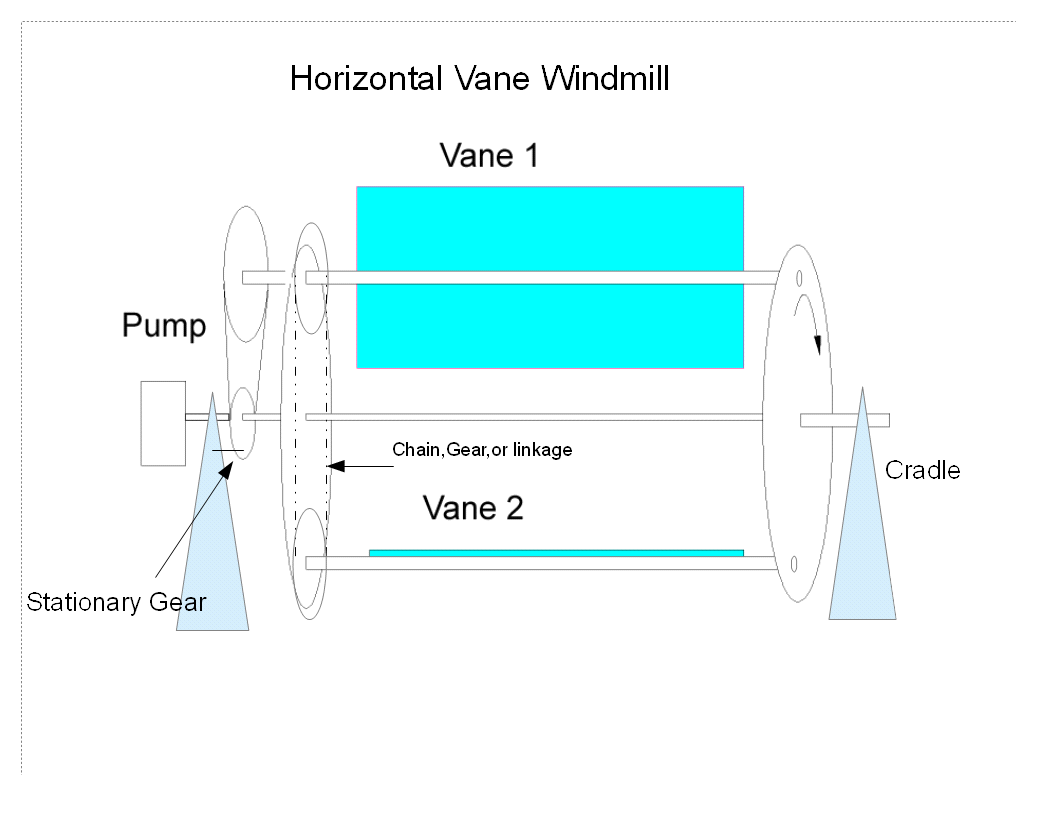
To do this, a simple bar system with or without cross bar would be erected (as shown below) to hold the vanes, potentially these could be built in tandem using recycled plastic sheets for the vanes. One goal of the project is to provide the CNC programs, engineering diagrams, and data needed to make the project possible for free to the public. Another goal is to explore the use of plasmajet cutting to provide low cost wind power kits and designs in general. 
In this design, all parts can be made with nothing more than some sprockets and a welder, no special vanes need to be cut out and common journal bearings could be used if conventional bearings or low friction magnetic bearings are not available. All parts could be cut out on a low cost plasmajet cutter if commercial sources are unavailable. Cloth or inexpensive materials, like recycled plastic, can be used to catch the wind since the frames can be square. A program has been created to show the motion of the windmill with multiple vanes, download here(zipped setup file with older VB6 runtime file 1.3MB) , or download here(without VB6 runtime file 250KB) . Note most Windows computers already have a VB6 runtime file installed. Direction can be wind stearable or stationary depending upon desired simplicity and constancy of wind. The tooth ratio for the sprocket is 2:1 Animated Gif (1.5MB).
This can also be implemented like a children's carousel, with most of the loading at a single central point. This is not a new idea, a quick search of the internet revealed globally more than a dozen prior art implementations using a chain drive to maintain vane angle. The oldest was a 16th century Chinese design for a vertical windmill using this mechanism. The single greatest advantage is the ability to use very, very large inexpensive surfaces to gain more power and the ability to gang these together using hydraulic or mechanical interconnects. A quick patent search reveals that this idea has been patented (see some of the patents) on numerous occasions beginning in 1918. A simple version can be seen in patent #4494007 in 1985 and #4282944 in 1981. Both solid linkages and cam interconnects for the vanes have been published using a 2:1 sprocket drive to maintain angle. Patent #20090081061 shows an alternate but unwieldy cog operated system. A timing belt type interconnect to the various vanes is shown in multiple patents including 20090257874. Multiple torturous gear mechanisms including planetary drives have also been used to accomplish similar ends. Here is a short filmclip made for the Gigabot 3D printer contest.
Considering the current and prior art dating back to the 16th century Chinese designs, and considering no profit is being sought, utilizing a 2:1 ratio chain drive to maintain vane angle should not pose an intellectual property liability. Most patents showing this idea from the past century are identical and have since expired. Therefore, it is a good place to start. More recent patents differ significantly from the design below so as to avoid most confusion.